by Daniel Berkemeyer – Productdesigner
In our project we are thinking about milling a part of the interieur, so I started sketching….
by Daniel Berkemeyer – Productdesigner
I am very sorry, but in the moment there is so much work for the milling specialists, that there is no chance to mill the 1:1 model, maybe in 1 or 2 weeks there is a possibility to do it…
But meanwhile I will show you some clay basics and tips around frequently asked questions. Today I want to start this with 2 options for the presentation of a clay model as an alternitive to the very expensive Dynoc-foil
First the use of SilverPeel:
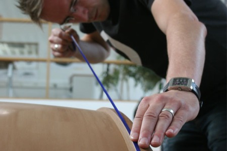
Taping all surrounding surfaces
When you have highlighted and finished the area on which you want to apply Silverpeel, protect all edges and surrounding surfaces with tape. Do not forget to cover the rest of the model with paper or plastic foil because of the spray drift.
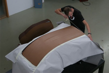
paper cover
Now you can lacquer the surface with an ordinary airgun. You have to follow the same rules like lacquering with acryl or water-based colours.
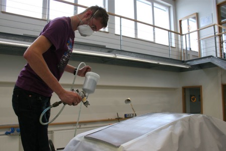
lacquering
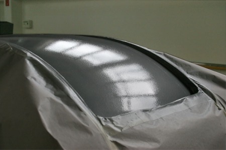
wet ClayPeel
As you can see in the reflection, the fresh added peel is still very rough and high glossy.
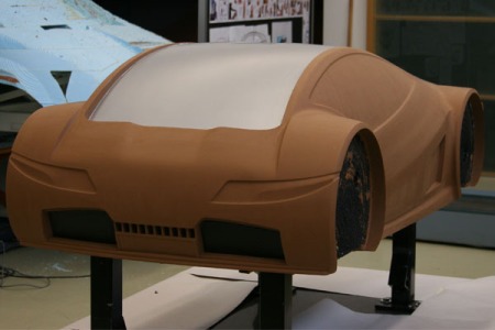
dried ClayPeel
When the ClayPeel has dried, which needs some hours, the surface is smoother and matt. Every mistake in your finished clay surface will be detected now easily, also tiny cracks and so on.
One more little advise: in negative edges, like in this case, you have to remove carefully the tape as long as the peel is still wet or make an exact cut with a scalpel in the edge. If not, the peel will stick to your tape and ruin the peel edge.
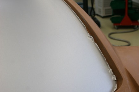
ruined peel edge
Another posibility is the use of ClayPeel (blue) as a primer and lacquering the dry ClayPeel surface with standard car paint. You can use water-based and acrylic-based colours. After every layer you can polish the surface with wet sand paper and seal it with clear varnish. The more layers you add, the better the surface will be. With this technique you can create the illusion of a real painted car and after the presentation you can peel off the whole lacquering almost traceless.
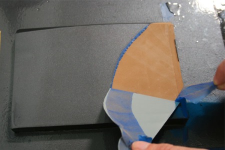
water-based lacquering on ClayPeel
by Daniel Berkemeyer – Productdesigner
Detail work is now finished and I can present you a rendering of the Data set I gave the CAM Expert. The last missing parts were the new door openers and the tank cap. I hope next week I can show you here a video of the fullscale milling…
by Daniel Berkemeyer – Productdesigner
The design steps forward and we are very close to start milling the fullscale model. Yesterday I made the last door joints and openers, name logo tag, new tire texture and a new colouring. I wanted to change the colour ambience from a warm “coffee” brown to a more fresh, dynamic lime green on the white car. This colour is not only a cold caipirinha on a tropical sand beach – green is also the colour we associate to a healthy envionment and its protection – for me one of the most important things in every project. There are a lot of thoughts about the technique of this car, but thats not the subject of this blog. Nevertheless I am very glad about using this coloured subtile hint…
The name logo evolved very fast. From “Kolb Technology eins” to “kt one”, it was only a short way to a simple “one” where the o is our company logo. I like that because its so simple and straight. On the grill I wanted to place it like a jewel on a tooth, in the beautiful smile of a girl.
by Claus Michelfeit – Dipl.Ing.(Univ) Software Manager
We used the old CAD model to create the milling programs with a negative offset to remove the clay. Please beware, that even that we have to remove material between 10 and 60mm, we are running the Studioline S with a very high feed rate to save time. Even if we reach the foam underneath the clay, this is no problem for the stability of the machine.
by Daniel Berkemeyer – Productdesigner
Today I designed new, better fitting frontlights and extend the joint on it´s end to mark the hood. This I think highlights the shape of the front very good. Another important part – the mirrors – where done yesterday. These tiny changes bring life to the bodysite and emphasize the hole design very gently. I also started thinking about where and how I should bring on our companys logos and I didn´t want to make another “bling, bling” chrome one (maybe for the trunk-opener…) so I integrated it into the laquering. I don´t know if I still like that in two weeks, but for the moment I love it. The next days I will spend with the blank bodyside and bring in the doors and so on…
Following there are some head light studies. These studies where my base for the light design.
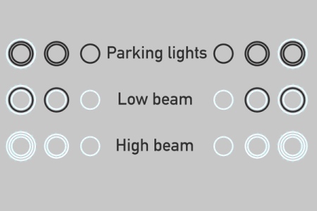
light Scheme
by Claus Michelfeit – Dipl. Ing. (Univ.) Software Manager
After finishing the shape in the 1:4 model we scanned the clay model using a 3D line scanner. In the video, the scanner is mounted on an arm which allows any degree of freedom through its 6 rotating axes. This scanner could alternatively also be used with a laser tracking system or could also be mounted on the milling machine.
You can see the scan line on the clay model and the resulting point cloud on the screen right to the model. From this point cloud, we can automatically create a STL file that we use for creating a 1:1 data model to machine our shape in full-scale.
by Daniel Berkemeyer – Productdesigner
Today I can present the first computer-rendering made in Rhino/Flamingo. Nothing final, just a co – product of splining.
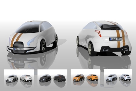
Preview
By Daniel Berkemeyer – Productdesigner
Before we can start milling our full scale model, even the foam of the substructure, we have to prepare or rather rework what we got from the Laser-scanner. Because the only thing a laser creates are points. Sure, a lot of – but for the next step we need surfaces and the better the quality of them the better the car will look. This includes also the perfect run of all edges. A beautiful reflection in the lacquering that shows everything in the environment, clouds, trees, street-markings occurs only on a perfect surface, called “class A surface”. At the end of the whole modelling process, the complete car will be finished and highlighted by hand, but the “class A surfaces” are a good base.
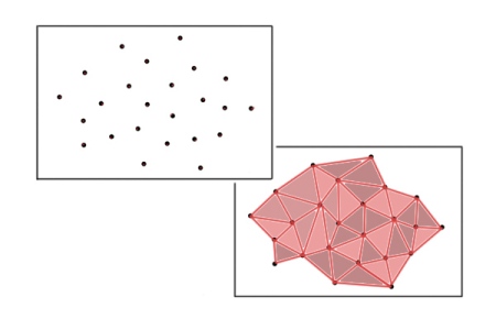
Pointcloud - STL Mesh
Normally the first step to surfaces is the compilation to stereolitography, short stl. This means that all points get connected to small triangles and a small surface between them. The denser the points the exacter the surface. Of course on a stl you can create milling-paths, but in our case, the scan-data is enlarged from a quarter-scale model to full-scale. So the distance of the triangles gets also four times bigger and a minor mistake in the smaller model become huge in the fullscale.
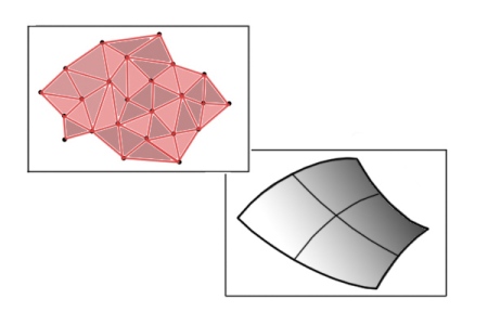
STL mesh - Class A Surface
On the base of our stl we can now create good surfaces with a NURBS CAD program, where we fit new curvature splines on the “rough” stl shape.
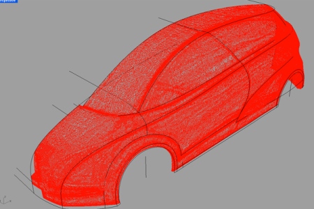
stl dataset
When you have fitted the splines on the stl mesh you can build “real” surfaces.
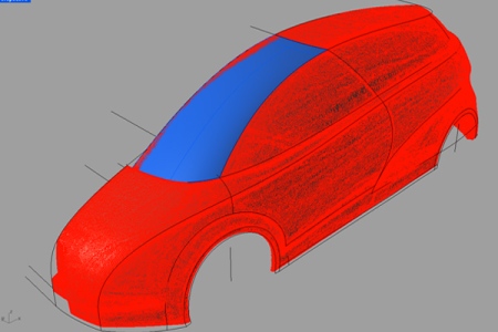
Windscreen surface class A
If it is possible the surface should be a “single span surface”, wich means with the lowest curve degree. Now, in CAD you have the possibility to rework all your edges and joints until you are satisfied with all of them.
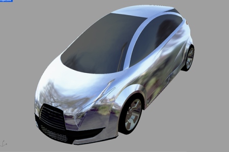
reworked "splined" model
You can give this dataset to a CAM expert and look forward to the first surfaces in 1:1.
by Daniel Berkemeyer – Productdesigner
In the evolve of our project, yesterday i made a new drawing. On this base I start serious thinking about door openers, logos and other details.
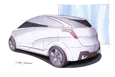
Designsketch